
This chapter describes how to plan for host definition and 2216 ESCON and Parallel Channel Adapter (PCA) support. It includes the following sections:
| Note: | UDP+ is not supported on a Parallel Channel Adapter (PCA). |
This section provides information to help you plan for host definition. It includes information for system definition from the host perspective and information for definition from the 2216 perspective.
Before you can attach the 2216 to a channel, the host system must be configured correctly. The following series of steps is required to define the 2216 connection to the host. These definition steps should be done by your system programmer.
After the host definitions are complete, you must configure the 2216 channel interfaces using the command line interface, or using the configuration program described in Configuration Program User's Guide for Nways Multiprotocol and Access Services, GC30-3830. Many of the parameters which you provide when you configure the 2216 must match corresponding parameters in the host definition.
Finally, the stations will need to be configured to communicate through the 2216 to the host applications.
The following sections describe host definition and provide sample host configuration statements.
The following sections describe examples of IOCP definitions for the 2216 with channel adapters. The output of the IOCP device definitions (I/O Configuration Data Set or IOCDS) can be generated using MVS, VM, VSE, or in a stand-alone environment. Refer to the IBM ES/9000 and ES/3090 Input/Output Configuration Program User's Guide Volume A04, GC38-0097, for details.
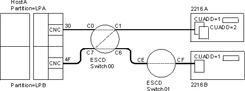
Figure 19 shows an example of an ESCON configuration. The S/390 host is divided into two logical partitions (LP): LPA and LPB. A connection on path 30 is configured between LPA and 2216A through ESCD switch 00. LPA is attached to ESCD port C0 and 2216A is attached to port C1. The connection between port C0 and C1 is dynamic.
Figure 19. ESCON Channel Configuration Example
 |
LPB on path 4F has a connection with 2216A through ESCD switch 00, and a connection with 2216B through ESCD switches 00 and 01. The connection between ports C7 and C6 is dynamic; the connection between ESCD ports CE and CF is dedicated.
The following example definitions match Figure 19:
Channel path definitions:
         CHPID      PATH=((30)),TYPE=CNC,PART=(LPA),SWITCH=00
         CHPID      PATH=((4F)),TYPE=CNC,PART=(LPB),SWITCH=00
Control unit and device definition for the 2216, with logical addressing = 1 for 2216A:
         CNTLUNIT   CUNUMBR=500,PATH=30,UNIT=3172,LINK=C1,         X
                    UNITADD=(00,32),CUADD=1
         IODEVICE   ADDRESS=(500,32),CUNUMBR=500,UNIT=3172,        X
                    UNITADD=00
Control unit and device definition for the 2216 with logical addressing = 2 for 2216A:
         CNTLUNIT   CUNUMBR=600,PATH=4F,UNIT=3172,LINK=C1,        X
                    UNITADD=(00,32),CUADD=2
         IODEVICE   ADDRESS=(600,32),CUNUMBR=600,UNIT=3172,       X
                    UNITADD=00
Control unit and device definition for the 2216, with logical addressing = 1 for 2216B:
         CNTLUNIT   CUNUMBR=620,PATH=4F,UNIT=3172,LINK=C6,         X
                    UNITADD=(20,32),CUADD=1
         IODEVICE   ADDRESS=(620,32),CUNUMBR=620,UNIT=3172,        X
                    UNITADD=20
The IOCP macroinstructions in the example:
Considerations:
Figure 20 shows an example of an ESCON configuration using the ESCON Multiple Image Facility (EMIF). The S/390 host is divided into two logical partitions (LP): LPA and LPB. Both LPA and LPB are connected on path 30 to 2216 A through switch 00.
Figure 20. EMIF Host Configuration Example
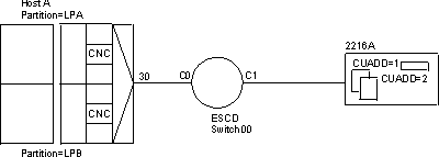 |
The following example definitions match Figure 20:
Channel path definitions:
CHPID PATH=((30)),TYPE=CNC,PART=(LPA,LPB),SWITCH=00
Control unit and device definition for the 2216, with logical addressing = 1 for 2216A:
         CNTLUNIT   CUNUMBR=500,PATH=30,UNIT=3172,LINK=C1,         X
                    UNITADD=(00,32),CUADD=1
         IODEVICE   ADDRESS=(500,32),CUNUMBR=500,UNIT=3172,        X
                    UNITADD=00
Control unit and device definition for the 2216, with logical addressing = 2 for 2216A:
         CNTLUNIT   CUNUMBR=620,PATH=30,UNIT=3172,LINK=C1,         X
                    UNITADD=(20,32),CUADD=2
         IODEVICE   ADDRESS=(620,32),CUNUMBR=620,UNIT=3172,        X
                    UNITADD=20
The IOCP macroinstructions in the example:
Considerations:
Figure 21 shows an example of a simple Parallel Channel Adapter configuration where the channel type is identified as a block multiplexer channel, TYPE=BL, on path 5.
Figure 21. Parallel Channel Adapter Configuration Example
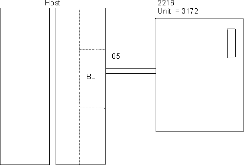 |
The IBM 2216 I/O device unit appears to the host as 3172 and must be defined as a 3172.
The following example definitions match Figure 21:
         CHPID      PATH=((05)),TYPE=BL
         CNTLUNIT   CUNUMBR=640,PATH=05,                           X
                    PROTOCL=S4,UNIT=3172,                          X
                    SHARED=N,UNITADD=((40,32))
         IODEVICE   UNIT=3172,ADDRESS=((640,32)),                  X
                    STADET=N,CUNUMBER=640,TIMEOUT=Y
The IOCP macroinstructions in the example:
Considerations:
The allowable device address range is 00 through FF. Each 2216 PCA can support a maximum of 32 subchannels. The 2216 PCA does not require a range of 32 addresses, it only requires that the addresses defined at the host computer map to the address or addresses configured for the 2216 PCA. The addresses used cannot overlap addresses used by other control units or PCAs cabled to the same CHPID or channel.
The transfer mode and channel transfer speed specified for the PROTOCL parameter must conform with the PCA setting for transfer mode and channel transfer speed.
The following definitions apply to a 2216 with a channel adapter.
The 2216 must be defined to a VM/SP operating system. This definition is accomplished by updating the real I/O configuration file (DMKRIO) with entries for the 2216 in the RDEVICE and the RCTLUNIT macros. In the following example, 640 is the base unit address and the size of the address range is 32.
RDEVICE ADDRESS=(640,32),DEVTYPE=3088
RCTLUNIT ADDRESS=640,CUTYPE=3088,FEATURE=32-DEVICE
The 2216 must be defined to a VM/Extended Architecture (VM/XA or VM/ESA operating system. This definition is accomplished by updating the real I/O configuration file (HCPRIO) with an entry for the 2216 in the RDEVICE macro. In the following examples, 640 and 2A0 are base control unit addresses. The address range size, as defined in the UCW or IOCP, is 8 in both examples.
The following example is a VM/XA HCPRIO definition:
RDEVICE ADDRESS=(640,8),DEVTYPE=CTCA
The following example is a VM/ESA HCPRIO definition:
RDEVICE ADDRESS=(2A0,8),DEVTYPE=CTCA
| Note: | To define a 2216 on an MVS/ESA system with HCD, see 2216 Definition for MVS/ESA with HCD |
The 2216 must be defined to an IBM Multiple Virtual Storage/Extended Architecture (MVS/XA) or MVS/ESA operating system. This definition is accomplished by updating the MVS Control Program with an entry for the 2216 in the IODEVICE macro.
For ESCON channels, an example IODEVICE macro is:
IODEVICE UNIT=3172,ADDRESS(540,8)
For parallel channels, an example IODEVICE macro is:
IODEVICE UNIT=CTC,ADDRESS(640,8)
The base control unit addresses are 640 and 540. The address range size, as defined in the UCW or IOCP, is 8 in both examples.
The hardware configuration definition (HCD) component of MVS/ESA SP Version 4.2 and 4.3 with APAR #OY67361 offers an improved method of defining system hardware configuration for 2216. Several complex steps required for entering hardware configuration data can be accomplished using an interactive dialog with HCD.
The required configuration data for the 2216 is:
IODEVICE UNIT=3172,ADDRESS(740,8)
IODEVICE UNIT=CTC,ADDRESS(840,8)
IODEVICE UNIT=SCTC,ADDRESS(A40,8)
Notes:
The 2216 must be defined to a VSE/ESA operating system. This definition is accomplished by supplying an ADD statement for each channel unit address at initial program load (IPL) time. Code the device type on the ADD statement as CTCA,EML as shown in the following example:
ADD 640,CTCA,EML
The base control unit address is 640 in the example. For the number of channel unit addresses added, increment the IOTAB storage macro by this count.
The section has configuration definitions with samples of host definitions required to connect to the 2216 channel adapter.
TCP/IP can connect to the 2216 channel adapter using either LCS or MPC+. When using MPC+, TCP/IP in the host goes through VTAM to the 2216.
| Note: | When referring to MPC+, the host uses the term HPDT MPC while the 2216 uses the term MPC+. |
TCP is configured on a host by modifying the TCP/IP profile. The default name for the TCP/IP profile data set is TCPIP.PROFILE.TCPIP for MVS and PROFILE TCPIP for VM. Each channel connection requires:
See the OS/390 TCP/IP OpenEdition publications for more information on configuring TCP/IP.
These are the statements required to configure TCP/IP on the host when using LCS:
The format of the DEVICE and LINK statements are:
  DEVICE devicename LCS subchannel
  LINK   iplinkname LANtype LANnumber devicename
where:
Specify IP addresses for each channel connection using the following format:
HOME hostipadd iplinkname
where:
| Note: | This IP address must be a unique address in the same IP subnetwork as the corresponding IP address coded in the 2216. |
Specify routing information if you are not using the ROUTED server.
GATEWAY network first hop driver packet size subn mask subn value
where:
An equal sign (=) meaning that messages are routed directly to destinations on that network or directly to that host. This is not supported for DEFAULTNET.
The Internet address of a gateway or router that you can reach directly, and that forwards messages for the destination network or host.
Start all the interfaces:
START devicename
where:
DEVICE LCS1 LCS   108
LINK   TR1  IBMTR 0 LCS1
HOME
    16.51.136.199 TR1      (1)
GATEWAY
    16.51.136.201 = TR1 4000  HOST    (2)
    DEFAULTNET 16.51.136.201 TR1 4000 0
START LCS1
(1) 16.51.136.199 is in the same IP subnetwork as the 2216 LCS interface's IP address.
(2) 16.51.136.201 is the 2216 LCS interface's IP address.
These are the statements required to configure TCP/IP on the host when using MPC+:
  DEVICE devicename MPCPTP
  LINK   iplinkname MPCPTP devicename
where:
Specify IP addresses for each channel connection using the following format:
HOME hostipadd iplinkname
where:
| Note: | This IP address must be a unique address in the same IP subnetwork as the corresponding IP address coded in the 2216. |
Specify routing information if you are not using the ROUTED server.
GATEWAY network first hop driver packet size subn mask subn value
where:
An equal sign (=) meaning that messages are routed directly to destinations on that network or directly to that host. This is not supported for DEFAULTNET.
The Internet address of a gateway or router that you can reach directly, and that forwards messages for the destination network or host.
Start all the interfaces:
START devicename
where:
For MPC+:
DEVICE IPTRL1 MPCPTP
LINK   LINK1 MPCPTP IPTRL1
HOME
    198.10.70.199 LINK1    (1)
GATEWAY
    198.10.70.203 = LINK1 16000 HOST    (2)
    DEFAULTNET 198.10.70.203 LINK1
START IPTRL1
(1) 198.10.70.199 is in the same IP subnetwork as one of the 2216 MPC+ interface's IP addresses.
(2) 198.10.70.203 is one of the 2216 MPC+ interface's IP addresses.
The following is an example of TCP/IP definitions that would be provided to the host computer in the TCP/IP Profile data set to configure an LCS device. The default name for the TCP/IP profile data set is TCPIP.PROFILE.TCPIP for MVS and PROFILE TCPIP for VM.
First, 2216 devices and links are defined to TCP/IP.
There is a DEVICE statement for each subchannel pair that is used to access 2216s. The first address specified must be an even address. In this example, two devices (subchannel pairs) are defined: one at address 640 and one at address 642. These devices could be in the same or different 2216s. A device type of LCS (LAN Channel Station) is used to define these devices to TCP/IP.
There is a LINK statement for each LAN adapter that is accessible from these devices. In this example, one Ethernet/802.3 Adapter is assigned to the device using subchannels 640 and 641, two Token-Ring adapters are assigned to the device using 642 and 643, and one FDDI adapter using 644 and 645. These two Token-Ring adapters are in the same 2216 because they are associated with the same device. The LINK number for each adapter (0 and 1 in this example) is assigned by the 2216 when you add an adapter to a profile.
| Note: | Two subchannel addresses are required for sending and receiving (for example, 640 and 641), but only the first address is defined. |
         DEVICE LCS1 LCS 640
         LINK ETH1 ETHERor802.3  0 LCS1
         DEVICE LCS2 LCS 642
         LINK TR1  IBMTR     0 LCS2
         LINK TR2  IBMTR     1 LCS2
         DEVICE LCS3 LCS 644
         LINK FD1  FDDI      0 LCS3
| Note: | In this example, 0 and 1 are the LAN numbers for these connections. |
This section of the example TCP/IP profile defines the local host internet addresses:
         HOME

         193.5.2.1      ETH1
         130.50.75.1    TR1
         130.50.76.1    TR2
         195.10.70.1    FD1
This section of the example TCP/IP profile represents the LAN/WAN gateway definition:
         GATEWAY

         Network  First hop Driver  Packet Size Subnet mask Subnet value
         193.5.2     =      ETH1    1500           0
         130.50      =      TR1     2000        0.0.255.0   0.0.75.0
         130.50      =      TR2     2000        0.0.255.0   0.0.76.0
         195.10      =      FD1     4000        0.0.255.0   0.0.70.0
This section of the example TCP/IP profile activates the LCS devices:
         START LCS1
         START LCS2
         START LCS3
The following examples illustrate various ways that LAN adapters can be specified and linked to subchannel pairs in the TCP/IP profile.
Two LCS devices for the two subchannel pairs 40,41 and 42,43 and four LAN adapters are defined in the 2216 as follows:
       DEVICE LCS1 LCS 640
       LINK ETH1 ETHERNET 0 LCS1
       LINK ETH2 ETHERNET 1 LCS1
       DEVICE LCS2 LCS 642
       LINK TRN1 IBMTR    0 LCS2
       LINK TRN2 IBMTR    1 LCS2
Four LCS devices for the four subchannel pairs 40,41; 42,43; 44,45; and 46,47 and four LAN adapters are defined in the 2216 as follows:
         DEVICE LCS1 LCS 640
         LINK ETH1 ETHERNET 0 LCS1
         DEVICE LCS2 LCS 642
         LINK ETH2 ETHERNET 1 LCS2
         DEVICE LCS3 LCS 644
         LINK TRN1 IBMTR    0 LCS3
         DEVICE LCS4 LCS 646
         LINK FD1  FDDI      0 LCS4
One LCS device for the subchannel pair 40,41 and four LAN adapters are defined in the 2216 as follows:
         DEVICE LCS1 LCS 640
         LINK ETH1 ETHERNET 0 LCS1
         LINK ETH2 ETHERNET 1 LCS1
         LINK ETH3 ETHERNET 2 LCS1
         LINK ETH4 ETHERNET 3 LCS1
The following is an example of TCP/IP definitions that would be provided to the host computer in the TCP/IP Profile data set to configure an MPC+ device. The default name for the TCP/IP profile data set is TCPIP.PROFILE.TCPIP for MVS and PROFILE TCPIP for VM.
First, in the VTAM host, define a TRL over which TCP/IP should run.
         IPTRL VBUILD TYPE=TRL
         IPTRL1 TRLE LNCTL=MPC,
                MAXBFRU=6,
                READ=(06),
                WRITE=(07)
                REPLYTO=3.0
Notes:
There is a DEVICE statement for each TRL that is to be used by TCP/IP.
DEVICE IPTRL1 MPCPTP
There is a LINK statement for each TCP/IP local host internet address using the TRL. For a given TCP/IP stack, there can only be one LINK statement per TRL.
LINK LINK1 MPCPTP IPTRL1
This section of the example TCP/IP profile defines the local host internet addresses and associates the addresses with a link:
        HOME

        198.10.70.199 LINK1 (1)
(1) 198.10.70.199 is in the same IP subnetwork as one of the 2216 MPC+ interface's IP addresses.
This section of the example TCP/IP profile represents the LAN/WAN gateway definition:
   GATEWAY

   Network        First hop      Driver  Packet Size  Subnet mask  Subnet value
   198.10.70.203    =            LINK1   16000        HOST   (1)
   DEFAULTNET     198.10.70.203  LINK1   16000        0
(1) 198.10.70.203 is one of the 2216 MPC+ interface's IP addresses.
This section of the example TCP/IP profile activates the MPC+ device:
START IPTRL1
| Note: | Prior to activating the device, activate the associated TRL if it is not already active. |
| Important! |
|---|
|
Before you configure your S/390 host for HPDT UPD, you must have APAR #OW31305 installed. |
HPDT UDP can connect to the 2216 only through an ESCON Channel Adapter using MPC+.
Notes:
HPDT UDP is configured and run using OS/390 TCP/IP OpenEdition (OE) on the host. Therefore, OS/390 TCP/IP OpenEdition must be installed on the host.
HPDT UDP commands are used to configure and control HPDT UDP resources. See IBM OS/390 TCP/IP Update Guide for details on installing and using OE for HPDT UDP.
To configure and activate an HPDT UDP connection on the 2216, issue the oeifconfig command, shown in the following example.
oeifconfig interface_name source_IP_address destination_IP address mtu nnnn
where:
This will cause the TRL to be activated if it is not already active.
| Note: | See "Configuring the VTAM Host for MPC+ for IP" for information about TRLs. |
This local IP address must be in the same IP subnetwork as the IP address coded for the UDP+ MPC+ network handler in the 2216.
This destination IP address must equal the IP address coded on the UDP+ MPC+ network handler in the 2216.
This mtu size must be equal to Maxdata coded on the UDP+ MPC+ network handler in the 2216. If the values are not equal, then the HPDT UDP connection will not come up.
| Note: | Because this is a point-to-point connection, there is no need to code the netmask parameter on this command. |
First, in the VTAM host, define a TRL over which HPDT UDP should run.
         UDPTRL VBUILD TYPE=TRL
         TRL1   TRLE LNCTL=MPC,
                MAXBFRU=9,
                READ=(EA0),
                WRITE=(EA1),
                REPLYTO=3.0
| Note: | See "Configuring the VTAM Host for MPC+ for IP" for more details. |
Next, go to the OE environment and issue the following command:
oeifconfig trl1 198.10.60.199 198.10.60.203 mtu 16384
Configuring the VM or MVS host requires entries in two VTAM control blocks:
For more information on configuring VTAM, refer to IBM VTAM Resource Definition Reference.
Defining an XCA major node requires coding VTAM definition statements to define the following characteristics:
You must code a VBUILD definition statement and a PORT definition statement for the major node, and code GROUP, LINE, and PU definition statements for minor nodes.
You must also assign service access points (SAPs) to be used for each virtual channel to a LAN or emulated LAN.
The switched major node definition file defines the workstations that VTAM will be able to access through the 2216 channel adapter, and identifies:
To define the 2216 LAN/WAN gateway to VTAM, the appropriate LAN adapter in the IBM 2216 must be associated with a subchannel address. This association is defined to VTAM in a major node definition that is supported by VTAM Version 3 Release 4 and VTAM Version 4 Release 1.
Configuring the VM or MVS host requires entries in two VTAM control blocks, the XCA Major Node Definition File and the Switched Major Node Definition File. See "VTAM Control Blocks Used to Configure LSA at the Host" for a description of the purpose of these control blocks and references to VTAM publications
ROUTE6B1 VBUILD TYPE=XCA
PORT6B1  PORT   CUADDR=0CB,ADAPNO=0,TIMER=60,SAPADDR=08,               C
               MEDIUM=RING
GRP6B1   GROUP  DIAL=YES
************************
LN06B001 LINE  ANSWER=ON,CALL=INOUT,ISTATUS=ACTIVE
PU06B001 PU    ISTATUS=ACTIVE
Notes:
PS06SW  VBUILD TYPE=SWNET
PS06PU  PU ADDR=01,IDBLK=05D,IDNUM=54445,MAXOUT=7,PACING=0,VPACING=0,  C
               SSCPFM=USSSCS,MAXDATA=4105,MODETAB=LMT3270,MAXPATH=1,   C
               ANS=CONT,ISTATUS=ACTIVE,DLOGMOD=B22NNE
PS06LU2 LU LOCADDR=02
PS06LU3 LU LOCADDR=03
PS06LU4 LU LOCADDR=04
PS06LU5 LU LOCADDR=05
Configuring the VM or MVS host requires entries in two VTAM control blocks, the XCA Major Node Definition File and the Switched Major Node Definition File. See "VTAM Control Blocks Used to Configure LSA at the Host" for a description of the purpose of these control blocks and references to VTAM publications.
P15AP63X VBUILD TYPE=XCA
PORT63X  PORT   CUADDR=0CD,ADAPNO=0,TIMER=60,SAPADDR=04,               C
               MEDIUM=CSMACD
GRP63X   GROUP  DIAL=YES
************************
LN630403 LINE  ANSWER=ON,CALL=INOUT,ISTATUS=ACTIVE
PU630403 PU    ISTATUS=ACTIVE
Notes:
LS601    VBUILD TYPE=SWNET
CS601   PU ADDR=02,CPNAME=C210,MAXOUT=7,PACING=0,VPACING=0,            C
               CPCP=YES,MAXDATA=4105,MODETAB=LMT3270,MAXPATH=10,       C
               CONNTYPE=APPN,DYNLU=YES
Configuring the VM or MVS host requires entries in two VTAM control blocks, the XCA Major Node Definition File and the Switched Major Node Definition File. See "VTAM Control Blocks Used to Configure LSA at the Host" for a description of the purpose of these control blocks and references to VTAM publications.
P15AP60X VBUILD TYPE=XCA
PORT60X  PORT   CUADDR=0CC,ADAPNO=1,TIMER=60,SAPADDR=04,               C
               MEDIUM=CSMACD
GRP60X   GROUP  DIAL=YES
************************
LN600403 LINE  ANSWER=ON,CALL=INOUT,ISTATUS=ACTIVE
PU600403 PU    ISTATUS=ACTIVE
LN600404 LINE  ANSWER=ON,CALL=INOUT,ISTATUS=ACTIVE
PU600404 PU    ISTATUS=ACTIVE
Notes:
PSK5SW  VBUILD TYPE=SWNET
PSK5PU  PU ADDR=03,IDBLK=05D,IDNUM=07251,MAXOUT=7,PACING=0,VPACING=0,  C
               DLOGMOD=B22NNE,                                         C
               SSCPFM=USSSCS,MAXDATA=2000,MODETAB=LMT3270
PSK5LU2 LU LOCADDR=02
PSK5LU3 LU LOCADDR=03
PSK5LU4 LU LOCADDR=04
PSK5LU5 LU LOCADDR=05
PSK5LU6 LU LOCADDR=06
Configuring the VM or MVS host requires entries in two VTAM control blocks, the XCA Major Node Definition File and the Switched Major Node Definition File. See "VTAM Control Blocks Used to Configure LSA at the Host" for a description of the purpose of these control blocks and references to VTAM publications.
P15AP60X VBUILD TYPE=XCA
PORT60X  PORT   CUADDR=0CC,ADAPNO=1,TIMER=60,SAPADDR=04,               C
               MEDIUM=CSMACD
GRP60X   GROUP  DIAL=YES
************************
LN600403 LINE  ANSWER=ON,CALL=INOUT,ISTATUS=ACTIVE
PU600403 PU    ISTATUS=ACTIVE
LN600404 LINE  ANSWER=ON,CALL=INOUT,ISTATUS=ACTIVE
PU600404 PU    ISTATUS=ACTIVE
Notes:
PS06SW  VBUILD TYPE=SWNET,MAXDLUR=20
PS06PU  PU ADDR=01,IDBLK=05D,IDNUM=54445,MAXOUT=7,PACING=0,VPACING=0,  C
               SSCPFM=USSSCS,MAXDATA=4105,MODETAB=LMT3270,MAXPATH=1,   C
               ANS=CONT,ISTATUS=ACTIVE,DLOGMOD=B22NNE
PS06LU2 LU LOCADDR=02
PS06LU3 LU LOCADDR=03
PS06LU4 LU LOCADDR=04
PS06LU5 LU LOCADDR=05
PSK5SW  VBUILD TYPE=SWNET
PSK5PU  PU ADDR=03,IDBLK=05D,IDNUM=07251,MAXOUT=7,PACING=0,VPACING=0,  C
               DLOGMOD=B22NNE,                                         C
               SSCPFM=USSSCS,MAXDATA=2000,MODETAB=LMT3270
PSK5LU2 LU LOCADDR=02
PSK5LU3 LU LOCADDR=03
PSK5LU4 LU LOCADDR=04
PSK5LU5 LU LOCADDR=05
PSK5LU6 LU LOCADDR=06
The following examples show XCA and SWNET macros that define the LAN major node for a Token-Ring adapter and an Ethernet adapter, respectively. In the examples:
The mode table and default mode entries are examples only. Be sure to use the mode tables and mode entries defined in your installation.
TRLAN1   VBUILD TYPE=XCA
PORT1    PORT   MEDIUM=RING,ADAPNO=0,CUADDR=644,TIMER=60,SAPADDR=4
GROUP1T  GROUP  DIAL=YES    * Switched Attachment
LINE1TA  LINE   ANSWER=ON,CALL=INOUT,ISTATUS=ACTIVE
PU1TA    PU     ISTATUS=ACTIVE
LINE1TB  LINE   ANSWER=ON,CALL=INOUT,ISTATUS=ACTIVE
PU1TB    PU     ISTATUS=ACTIVE
GROUP2T  GROUP  DIAL=NO     * Leased Definition
LINE2T   LINE   USER=SNA    * Multi-domain Connection
PU2T     PU     MACADDR=400000000001,TGN=1,SUBAREA=2,SAPADDR=4,PUTYPE=5
ENLAN2   VBUILD TYPE=XCA
PORT2    PORT   MEDIUM=CSMACD,ADAPNO=0,CUADDR=645,TIMER=60,SAPADDR=4
GROUP1E  GROUP  DIAL=YES    * Switched Attachment
LINE1EA  LINE   ANSWER=ON,CALL=INOUT,ISTATUS=ACTIVE
PU1EA    PU     ISTATUS=ACTIVE
LINE1EB  LINE   ANSWER=ON,CALL=INOUT,ISTATUS=ACTIVE
PU1EB    PU     ISTATUS=ACTIVE
GROUP2E  GROUP  DIAL=NO     * Leased Definition
LINE2E   LINE   USER=SNA    * Multi-domain Connection
PU2E     PU     MACADDR=400000000002,TGN=2,SUBAREA=2,SAPADDR=4,PUTYPE=5
The following examples are the switched major node definitions.
LS100SW VBUILD TYPE=SWNET,MAXGRP=400,MAXNO=400
CS100001 PU  ADDR=01,PUTYPE=2,MAXPATH=4,ANS=CONT,DLOGMOD=B22NNE,
         ISTATUS=ACTIVE,MAXDATA=521,IRETRY=YES,MAXOUT=7,
         PASSLIM=5,IDBLK=111,IDNUM=00001,MODETAB=LMT3270
         PATH  DIALNO=0104400000000004,GRPNM=GROUP1T
S00102   LU   LOCADDR=2
CS100002 PU  ADDR=02,PUTYPE=2,MAXPATH=4,ANS=CONT,DLOGMOD=B22NNE,
         ISTATUS=ACTIVE,MAXDATA=521,IRETRY=YES,MAXOUT=7,
         PASSLIM=5,CPNAME=MYNS2,MODETAB=LMT3270
         PATH  DIALNO=0104400000000005,GRPNM=GROUP1T
S00200  LU   LOCADDR=0,DLOGMOD=LU62MODE
S00202  LU   LOCADDR=2
CS100003 PU  ADDR=03,PUTYPE=2,MAXPATH=4,ANS=CONT,DLOGMOD=B22NNE,
         ISTATUS=ACTIVE,MAXDATA=521,IRETRY=YES,MAXOUT=7,
         PASSLIM=5,IDBLK=111,IDNUM=00003,MODETAB=LMT3270
         PATH  DIALNO=0104400000000006,GRPNM=GROUP1E
S00302   LU   LOCADDR=2
CS100004 PU  ADDR=04,PUTYPE=2,MAXPATH=4,ANS=CONT,DLOGMOD=B22NNE,
         ISTATUS=ACTIVE,MAXDATA=521,IRETRY=YES,MAXOUT=7,
         PASSLIM=5,IDBLK=111,IDNUM=00004,MODETAB=LMT3270
         PATH  DIALNO=0104400000000007,GRPNM=GROUP1E
S00402  LU   LOCADDR=2
CS100005 PU  ADDR=05,PUTYPE=2,MAXPATH=4,ANS=CONT,DLOGMOD=B22NNE,
         ISTATUS=ACTIVE,MAXDATA=521,IRETRY=YES,MAXOUT=7,
         PASSLIM=5,IDBLK=111,IDNUM=00005,MODETAB=LMT3270
         PATH  DIALNO=0104400000000008,GRPNM=GROUP1F
S00502   LU   LOCADDR=2
CS100006 PU  ADDR=06,PUTYPE=2,MAXPATH=4,ANS=CONT,DLOGMOD=B22NNE,
         ISTATUS=ACTIVE,MAXDATA=521,IRETRY=YES,MAXOUT=7,
         PASSLIM=5,IDBLK=111,IDNUM=00006,MODETAB=LMT3270
         PATH  DIALNO=0104400000000005,GRPNM=GROUP1F
S00602  LU   LOCADDR=2
For more information about VTAM definitions, see:
IBM VTAM V4R4 Network Implementation Guide, SC31-8370
IBM VTAM V4R4 Resource Definition Reference, SC31-8377
Configuring the VTAM host for MPC+ for APPN requires entries in two VTAM control blocks, the Local SNA Major Node and the Transport Resource List (TRL) Major Node, and a change to the VTAM start-up parameters. A TRL corresponds to an MPC+ Group. For more information on configuring VTAM, refer to IBM VTAM Resource Definition Reference.
Use the following definition statements to configure a local SNA major node in VTAM:
  UTYLSNA VBUILD TYPE=LOCAL
  UTYHCC1 PU     TRLE=UHCC1,XID=YES,CONNTYPE=APPN,CPCP=YES,HPR=YES
  BC4UTRL VBUILD TYPE=TRL
  UHCC1   TRLE LNCTL=MPC,                                              C
               MAXBFRU=n,                                              C
               READ=(xxx1,xxx2,...),                                   C
               WRITE=(yyy1,yyy2,...),                                  C
               REPLYTO=3.0
where:
The read and write subchannel numbers must be attached to those configured on the 2216 (for example, by way of a message operator mount or an attach command).
| Note: | A "read" subchannel to VTAM is a "write" subchannel to the 2216 and a "write" subchannel to VTAM is a "read" subchannel to the 2216. |
In the VTAM initialization file ATCSTRxx, where xx is defined by the user, define a network node:
NODETYPE=NN
Since high-performance routing (HPR) is being used, you also should add to this file:
HPR=YES
| Note: | Only APPN HPR is supported across the MPC+ interface. APPN ISR is not supported. |
To activate the APPN PU, activate the associated TRLE (if it is not already active) and then activate the PU.
See IBM VTAM Operation for information about VTAM Commands.
| Note: | UDP+ is not supported on a Parallel Channel Adapter (PCA). |
Configuring the VTAM host for MPC+ for TCP/IP or for HPDT UDP requires an entry in the VTAM Transport Resource List (TRL) Major Node control block. A TRL corresponds to an MPC+ Group. For more information on configuring VTAM, refer to IBM VTAM Resource Definition Reference.
   TRL    VBUILD TYPE=TRL
   TRL1   TRLE LNCTL=MPC,                                             C
          MAXBFRU=n,                                                  C
          READ=(xxx1,xxx2,...),                                       C
          WRITE=(yyy1,yyy2,...),                                      C
          REPLYTO=3.0
where:
| Note: | For both TCP/IP and HPDT UDP, MAXBFRU*4K must be greater than
Maxdata coded on the MPC+ network handler in the 2216.
See IBM OS/390 TCP/IP OpenEdition and IBM OS/390 Update Guide for additional restrictions regarding MAXBFRU. |
The read and write subchannel numbers must match those configured on the 2216 (for example, by way of a message operator mount or an attach command).
| Note: | A "read" subchannel to VTAM is a "write" subchannel to the 2216 and a "write" subchannel to VTAM is a "read" subchannel to the 2216. |
This section describes considerations for support of the 2216 and channel adapter in a network. Analyzing and resolving a communications problem between a channel adapter and a host or LAN may require you to initiate problem resolution procedures for the 2216.
The problem can be:
Indications of problems come from user reports, or indicators and displayed codes on the 2216 and other devices, or messages displayed by programs. These indications help you determine whether the problem is a hardware, software, or user problem. They also help you isolate the location (2216, LAN, host) and component (device, adapter, channel, or program) of the network that has the problem.
Determining the nature of the problem often indicates which procedures, tools, or additional information may be needed for resolution. The same tools, procedures, and information can also indicate the need to call for service. Problem resolution and service interfaces (NetView, SNMP Client) are available to the customer.
The 2216 ESCON channel adapter and PCA problem isolation procedures described in 2216 Nways Multiaccess Connector Service and Maintenance Manual, SY27-0350 should help you correct the problem, if possible, and determine when to call for service.
Whenever your network grows, shrinks, or rearranges, you may need to reconfigure host programs and 2216 profiles to:
The ESCON Channel Adapter and PCA provides the 2216 with access to SNA and TCP/IP host applications from LANs, WANs, and ATM.
Figure 22 shows a 2216 connected to a VTAM host through a channel adapter. Each ESCON channel adapter provides up to 64 subchannels and up to 32 associated virtual network handlers that can support LAN Channel Station (LCS), Link Services Architecture (LSA), and Multi-Path Channel (MPC+) protocols. Each Parallel Channel Adapter (PCA) provides up to 32 subchannels and up to 16 associated virtual network handlers. Each 2216 can contain up to four channel adapters.
Each ESCON Channel Adapter can provide connections to up to:
Each PCA can provide connection to one host or one logical host image.
Figure 22. 2216 Connected to a Host through an ESCON/PCA Channel Adapter - Logical View
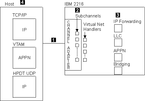 |
Each virtual network handler supports one of the following protocols:
For each LCS virtual network handler, you must define two subchannels, one for read and one for write; you can define up to 32 LCS virtual network handlers for each ESCON channel adapter and up to 16 for each PCA.
For each LSA virtual network handler, you must define at least one subchannel up to a maximum of 64 subchannels. You can define up to 32 LSA virtual network handlers for each ESCON channel adapter and up to 16 for each PCA.
For MPC+, you can define up to 64 subchannels. You must have at least one read subchannel and at least one write subchannel. You can define up to 32 MPC+ virtual network handlers for each ESCON channel adapter and up to 16 for each PCA.
Notes:
Once the channel adapter is installed and configured for LCS, LSA, and MPC+, it can provide:
| Note: | UDP+ is not supported on a Parallel Channel Adapter (PCA). |
Figure 23 shows the basic flow for a channel adapter with LCS and LSA configured, and Figure 24 shows the basic flow for a channel adapter for which MPC+ is configured.
Figure 23. 2216 Virtual Net Handlers for LCS and LSA
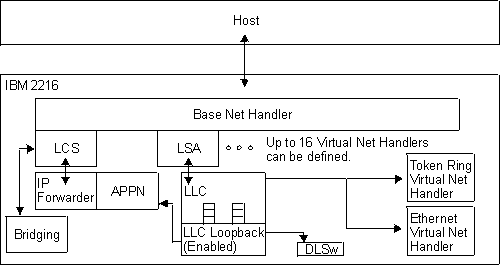 |
Figure 24. 2216 Virtual Net Handlers for MPC+
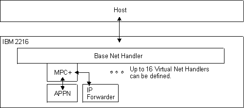 |
Figure 25 shows how TCP/IP data flows from the host, through LCS and other 2216 software components, and out to the LANs/WANs.
Figure 25. Configuring LAN Channel Station (LCS) Virtual Net Handlers. This figure shows LCS flow and highlights key parameters at the host and in the 2216.
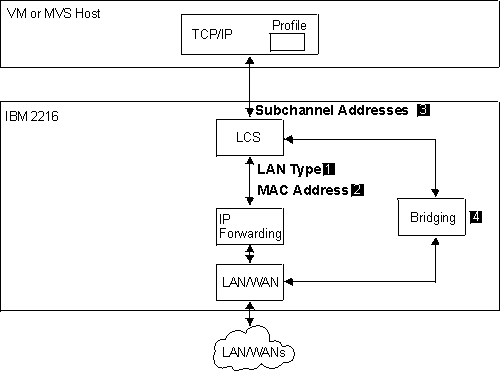 |
Figure 25 shows an LCS connection. To configure the 2216 for LCS:
| Note: | If the LAN type is Ethernet, then the MAC address must be in canonical format. |
You must configure an IP address and mask. Refer to Protocol Configuration and Monitoring Reference Volume 1.
There are optional parameters:
For information on the corresponding host definitions, see "Configuring the Host for TCP/IP".
TCP/IP Passthru bridges, rather than routes, IP frames received on an LCS
virtual network handler to a LAN or WAN interface. To use this feature,
you must configure bridging on the LCS virtual network handlers and the LAN
and WAN interfaces that you wish to interconnect. See Configuring and Monitoring Bridging in Protocol Configuration and Monitoring Reference Volume 1 for more information on configuring bridging. The type of bridging
you will configure depends on the LAN type of the LCS virtual network
interfaces. The following table shows the appropriate bridging
parameters for each LCS LAN type.
| LCS LAN Type | Bridging Type | Forward STE Frames |
|---|---|---|
| Token-Ring | Source Routing, Transparent, or both | Enabled |
| Ethernet | Transparent | N/A |
| FDDI | Transparent | N/A |
| Note: | The Spanning Tree protocol is automatically disabled on the LCS virtual network handler. |
Attention: You cannot configure both an IP address and bridging for an LCS. If you specify both, the configuration program operates as if you had specified only the IP address option. If you want to bridge IP frames, do not specify an IP address.
LCS Passthru allows the IBM 2216 to function as a 3172 replacement in TCP/IP networks. Frames received from a TCP/IP host are passed directly to a downstream LAN adapter, bypassing the IP router and bridging functions of the IBM 2216. IP and ARP frames received by a LAN adapter associated with the LCS passthru function are passed directly to the LCS net handler for delivery to the TCP/IP host. The IBM 2216 replaces the 3172 LCS function without requiring changes in IP network topology or adding additional bridge hops.
The following example describes LCS Passthru configuration:
*t 6
Gateway user configuration
Config>add dev esc
Device Slot #(1-8) [1]?3
Adding ESCON Channel device in slot 3  port 1 as interface #4
Use "net 4" to configure ESCON Channel parameters
Config>net 4
ESCON Config>add lcs
ESCON Add Virtual>?
LANtype
MAC address
MAXdata
BLKtimer
ACKlen
SUBchannels
ENable 3172 Emulation
Exit
ESCON Add Virtual>enable
Enabling LCS 3172 Emulation for network 5.
Please set the Network link using the "NET" command.
ESCON Add Virtual>?
BLKtimer
ACKlen
SUBchannels
DISable 3172 Emulation
NET link
Exit
ESCON Add Virtual>net 0
ESCON Add Virtual>sub add
Please add or configure one subchannel for an LCS virtual interface.
Although LCS requires two subchannels, it is only necessary to specify
one subchannel.  An adjacent subchannel will be chosen such that the two
subchannels will form a sequential pair with the write subchannel (device
address is even) before the read subchannel (device address is odd).
ESCON Config LCS Subchannel>?
LINk address (ESCD Port)
LPAR number
CU logical address
Device address
Exit
ESCON Config LCS Subchannel>link f7
ESCON Config LCS Subchannel>lpar 0
ESCON Config LCS Subchannel>cu 0
ESCON Config LCS Subchannel>dev 20
ESCON Config LCS Subchannel>ex
ESCON Add Virtual>ex
ESCON Config>list
Net:  5   Protocol: LCS    LAN type: Token Ring      LAN number:  0
          3172 Emulation is enabled.
          MAC address: Obtained from net 0
          Block Timer:    5 ms   ACK length:   10 bytes
ESCON Config>list all
Net:  5   Protocol: LCS    LAN type: Token Ring      LAN number:  0
          3172 Emulation is enabled.
          MAC address: Obtained from net 0
          Block Timer:    5 ms   ACK length:   10 bytes
          Read Subchannels:
          Sub  0   Dev addr: 21  LPAR: 0  Link addr: F7  CU addr: 0
          Write Subchannels:
          Sub  1   Dev addr: 20  LPAR: 0  Link addr: F7  CU addr: 0

ESCON Config>
Link Services Architecture (LSA) permits the VTAM host to communicate with the channel adapter in the 2216.
Figure 26 shows the four types of LSA connections. Their configuration is described in:
For information on the corresponding host definitions, see "VTAM Control Blocks Used to Configure LSA at the Host".
Figure 26. Configuring Link Services Architecture (LSA) Virtual Net Handlers
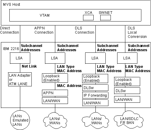 |
Figure 27. Configuring Virtual Net Handlers for LSA Direct Connection
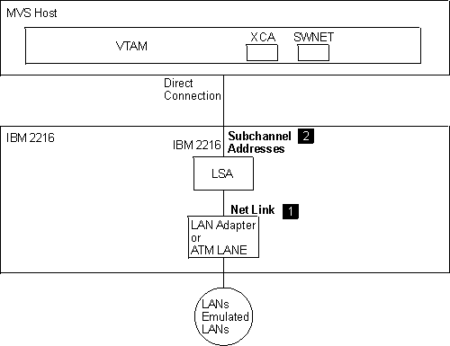 |
Figure 27 shows an LSA direct connection. To configure the LSA connection:
There are optional parameters:
| Note: | The LSA net will read its MAC address from the 2216 interface configured with the Net Link command. |
For information on the corresponding host definitions, see "Configuring an LSA Direct Connection at the VTAM Host".
Figure 28. Configuring Virtual Net Handlers for LSA APPN Connection
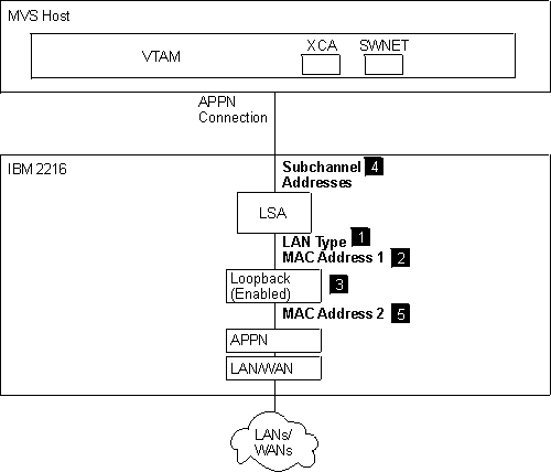 |
Figure 28 shows an LSA APPN connection. To configure the 2216 for an LSA APPN connection:
| Note: | You must configure the same LAN type for both the LSA net and the Loopback net. |
| Note: | If the LAN type is Ethernet, then the MAC address must be in canonical format. |
There are optional parameters:
| Note: | If the LAN type is Ethernet, then the MAC address must be in canonical format. |
For information on the corresponding host definitions, see "Configuring an LSA APPN Connection at the VTAM host".
Figure 29. Configuring Virtual Net Handlers for LSA DLSw Connection
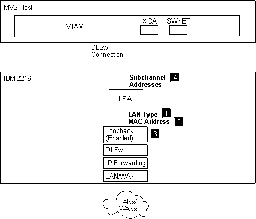 |
Figure 29 shows an LSA DLSw connection. To configure an LSA DLSw connection:
| Note: | If the LAN type is Ethernet, then the MAC address must be in canonical format. |
Enable DLSw, using the enable dls command.
Set the DLSw segment number using the set srb command. The DLSw segment number must be unique.
Add the remote DLSw TCP partner using the add tcp command.
Open the SAPs that will be used with the LSA loopback interface using the open command. The open command will prompt for an interface number. Input the interface number assigned to the LSA loopback interface that is defined for use with DLSw.
For a description of the DLSw configuration parameters, refer to the chapter entitled "Using and Configuring DLSw" in the Protocol Configuration and Monitoring Reference Volume 1 .
There are optional parameters:
For information on the corresponding host definitions, see "Configuring an LSA DLSw Connection at the VTAM Host".
Figure 30. Configuring Virtual Net Handlers for LSA DLSw Local Conversion
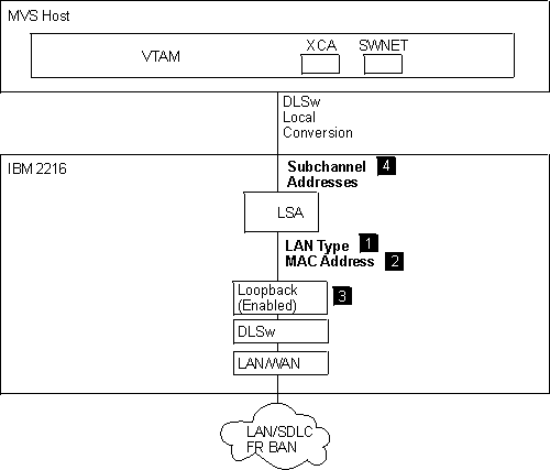 |
Figure 30 shows a configuration that supports LSA DLSw local conversion. To configure a 2216 for LSA DLSw conversion:
| Note: | If the LAN type is Ethernet, then the MAC address must be in canonical format. |
Enable DLSw, using the enable dls command.
Set the DLSw segment number using the set srb command. The DLSw segment number must be unique. The DLSw segment number must be different from segment numbers assigned to other interfaces.
Add the local DLSw TCP partner using the add tcp command.
Open the SAPs that will be used with the LSA loopback interface using the open command. The open command will prompt for an interface number. Input the interface number assigned to the LSA loopback interface that is defined for use with DLSW.
Opening SAPs and configuring bridging on the local LAN/WAN interfaces might be required. Opening the SAPs and configuring bridging permits incoming frames to be forwarded to DLSw.
| Note: | Each LSA interface can support up to 10240 LLC link stations per SAP. An LSA interface can support multiple SAPs. |
For a description of the DLSw configuration parameters, refer to the chapter entitled "Using and Configuring DLSw" in the Protocol Configuration and Monitoring Reference Volume 1.
There are optional parameters:
Multi-Path Channel+ (MPC+) permits the VTAM host to communicate with the channel adapter in the 2216. An MPC+ Group is a set of subchannels, containing at least one read and one write subchannel, whose end points converge at a common MPC+ image in the VTAM Host.
Figure 31. Different types of MPC+ Connections.
| Note: | UDP+ is not supported on a Parallel Channel Adapter (PCA). |
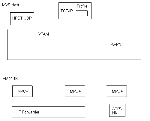 |
Figure 31 shows the three types of MPC+ connections. The following sections describe the types in more detail:
For information on the corresponding host definitions, see "Defining the 2216 to Host Programs".
To configure an MPC+ Group in the 2216, configure an MPC+ interface on a base ESCON or PCA interface.
| Note: | UDP+ is not supported on a Parallel Channel Adapter (PCA). |
Figure 32 shows MPC+ flow and highlights key parameters at the host and in the 2216.
Figure 32. Configuring Virtual Net Handlers for APPN over Multi-Path Channel+ (MPC+)
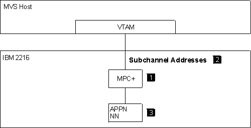 |
Figure 32 shows the parameters required to configure MPC+ for APPN.
(1) Configure the MPC+ Virtual Interface as described in "Configuring an MPC+ Virtual Interface".
(2) Configure subchannels for read and write connections to the host as described in "Configuring an MPC+ Subchannel".
| Note: | Do not enable UDP+ exclusive use on the MPC+ interface. Ignore the disable outbound protocol data blocking parameter. It does not apply and has no effect for APPN. |
There are optional parameters:
This is the amount of time that the MPC+ Group waits to hear from across the channel during XID2 and DISC exchanges before deciding that the other end of the channel is not answering and that this side should continue with the bring up or bring down of the MPC+ Group.
This timer is used to determine whether connection-oriented data is flowing smoothly across the connection on an MPC+ Group. The MPC+ control flows flow connection-oriented. Since these commands must have guaranteed delivery at the link level they flow connection-oriented and the Sequencing Interval timer is used to determine whether enough time has passed that checking of the delivery of connection-oriented traffic should be done.
(3) With the following exceptions, APPN is configured over the MPC+ interface as it is over other interface types:
For information on the corresponding host definitions, see "Configuring the VTAM Host for MPC+ for APPN".
Figure 33 graphically illustrates a UDP+ configuration over MPC+.
Figure 33. Configuring Virtual Net Handlers for UDP+ over MPC+
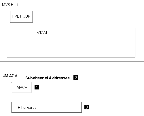 |
(1) Configure the MPC+ Virtual Interface as described in "Configuring an MPC+ Virtual Interface".
Enable UDP+ exclusive use on the MPC+ interface.
There are optional parameters:
This is the amount of time that the MPC+ Group waits to hear from across the channel during XID2 and DISC exchanges before deciding that the other end of the channel is not answering and that this side should continue with the bring up or bring down of the MPC+ Group.
This timer is used to determine whether connection-oriented data is flowing smoothly across the connection on an MPC+ Group. The MPC+ control flows are connection-oriented. Since these commands must have guaranteed delivery at the link level they flow connection-oriented and the Sequencing Interval timer is used to determine whether enough time has passed that checking of the delivery of connection-oriented traffic should be done.
| Note: | This value must equal the MTU coded for HPDT UDP in the host. |
(2) Configure subchannels for read and write connections to the host as described in "Configuring an MPC+ Subchannel".
(3) IP is configured over the MPC+ interface in the same manner that it is configured over other interface types; however:
| Note: | If more than one IP address is configured, the last one configured is the one that is used. |
For information on the corresponding host definitions, see "Configuring the Host for HPDT UDP:".
Figure 34 graphically illustrates a TCP/IP configuration over MPC+.
Figure 34. Configuring Virtual Net Handlers for TCP/IP over MPC+
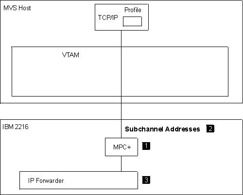 |
(1) Configure the MPC+ Virtual Interface as described in "Configuring an MPC+ Virtual Interface".
| Note: | Do not enable UDP+ exclusive use on the MPC+ interface. TCP/IP is configured on an MPC+ interface by virtue of configuring IP addresses for the MPC+ network handler and having the MPC+ interface not be configured for the exclusive use of UDP+. |
There are optional parameters:
This is the amount of time that the MPC+ Group waits to hear from across the channel during XID2 and DISC exchanges before deciding that the other end of the channel is not answering and that this side should continue with the bring up or bring down of the MPC+ Group.
This timer is used to determine whether connection-oriented data is flowing smoothly across the connection on an MPC+ Group. The MPC+ control flows flow connection-oriented. Since these commands must have guaranteed delivery at the link level they flow connection-oriented and the Sequencing Interval timer is used to determine whether enough time has passed that checking of the delivery of connection-oriented traffic should be done.
Notes:
(2) Configure subchannels for read and write connections to the host as described in "Configuring an MPC+ Subchannel".
(3) IP is configured over the MPC+ interface in the same manner that it is configured over other interface types; however:
For information on the corresponding host definitions, see "Configuring the Host for TCP/IP".
The following steps are required to configure the ESCON or PCA interface:
Once the 2216 ESCON or PCA configuration is complete,